

feed ME OR ELSE I DIE
an interactive plant sprinkler
This idea was born from my personal difficulty keeping my plants alive. Bo and I designed a device that would automatically feed our flower with water at daylight when the soil reaches a level of dryness indicating the need of water. If the soil is moisturized enough, the system wouldn’t be activated.
* The tube in the video is supposed to be wrapped around the plant but for demo purposes it is placed in the glass jar.
** The external light is to simulate the (bright) sunlight coming through the window.
*** The container is because of Halloween.
INSTRUCTION
The goal of this assignment is to show that you can make a simple interactive system with physical controls, and that you can keep a user engaged with your system. On a technical level, your project should show that you understand digital input and output, analog input and output, serial communication, and good physical interaction design principles. On a conceptual level, your project should help people to enjoy whatever setting it is designed for. Consider the behavior of the thing that the user will see, hear, or feel, and choose sensors that let you create that kind of behavior.
IDEATION
The concept of light feeding the plants plays a double meaning. Plants feed on light through synthesis and the photocell resistor would trigger the feeding of the plant literally and figuratively. Also, the “light” is feeding the plant with water, another source of energy for the plant.
How it works:
To avoid calculating when to water the plant or forgetting to water it altogether, this system is designed to water the plant when it reaches a certain level of dryness and can be programmed for specific conditions of each plant in particular depending on what it needs to thrive. In our case it was a less capricious plant which required water every 3-4 days and just enough water to keep it moist (we programmed the level of moisture it needed and the values of dryness for the capacitive sensor which will signal that the soil is dry). It was a plant that could be kept in direct sunlight (from a window) so we took that into account in design.
The photocell in the breadboard is the sensor programmed to read the light from the sun. If the soil is dry (the capacitive sensor in the soil checks for that), the photocell will activate the motor to pump water until the capacitive sensor values go up and signal to the motor to stop pumping water. It will override the photocell command. In this way the plant won’t receive more water than it needs despite the direct sunlight. The hose had small holes drilled in it for a slower and more uniform water flow, the coil of the hose around the flower is for a better distribution of water. The LED light is a user interface feature indicating, when ON, that the plant is wet (in other words in healthy condition), and when OFF - that it will require water soon.
The project required a lot of testing to determine the water flow speed, the amount, the level of light needed, and then the technical elements such as the circuit, the power supply, the resistors, etc., and programming the conditions ‘when’ - ‘ then’ - ‘if’ - ‘then’.
Application:
The most rewarding part of this project, besides figuring out how to keep my plants alive of course, it is the fact that it is a system that can be replicated and iterated upon for other plants and possibly even a greenhouse situation. Its application has POTENTIAL for more!


Test with a wet/dry papertowel to see if the sensor reads the data.
Testing resistors.

PROTOTYPING
This project was the first ‘physical computation’ project that was due at week 7 of the first semester of grad school, which means everything was new to us. It was an incredible amount of time in office hours with the residents and the teacher, and it was equally rewarding to see the idea come alive. This was a step-by-step process, making sure each part of it was working on its own, then combined together.
We got to learn to think technically as well as conceptually, and then design with the end user in mind so each element we chose for the product would align with the message, feel, and experience we wanted people to have when interacting with the device/interface. We also learned to problem solve, think outside the box, and find a way to manifest the idea into a tangible object.
So this is how we got it done after we came up with the idea:
MAKE SURE THE MOTOR WORKS. CONNECT TO BREADBOARD AND TEST.
Base connects to microcontroller A0 (analog) / D 14 (digital) through a transistor (1K).
The third leg (emitter/source) connects to the ground. They share the ground with the motor.
The middle one (drain/collector) is connected to the to DC Motor (black wire)
The red wire of the DC motor goes into the Power Supply.

It works. Both mechanical and Programming! Success!!! The DC lab that I did with Yoni the prior week helped a lot to know how to write the code and set up the circuit. Phil helped us a lot with conceptualizing the project from A to Z.
CONNECT SOIL SENSOR. DOWNLOAD ARDUINO LIBRARY. PROGRAM THE PHOTOCELL.
program the capacitive sensor;
2. add the code with our Arduino Data Info (pins) to the DC motor code;
3. configure the photocell into the breadboard and program it;
4. make sure all components work together.

The code and the capacitive sensor in the soil registering values.
TESTING!
For four days we left the flower with no water in order to measure the dryness of the soil. Unfortunately it seems someone did water it just this morning. The flower does look weak though. We can’t measure the driest point but will go with the numbers we tested last time.

We’ll need to figure out the power we’ll give to the motor. We’ll leave the device on and check the flower every day to see if it gets dry over the next few days and if and when the photocell will trigger the motor to water the plant.


We increased the capread to 1000 and the motor wouldn’t stop pumping water.
Observation: We raised the capacity to 1000 in order for the motor to be triggered and the motor pushed through a half of the container with water until we turned off the power. Maybe we need another condition for the motor to stop when the soil sensor registers values higher than 700? And then we put our trigger to water the plant at 600?
We suspect a few things that went wrong:
The first time we run the Arduino, the motor pumped three cycles and stopped. The next time we run the Arduino it worked without stopping. Why?
maybe the motor is at too high of a power? We didn’t check what that was but it was somewhere in the middle of the dial.
The question is, why the motor didn’t stop on its own?
How do we power the arduino when we are not next to the plant?
We’ll need to gauge her water intake as all succulent plants are ‘individuals’ according to Tanika (a fellow ITP interested in plants).

TROUBLESHOOTING THE PROBLEMS:
Me and Bo tried to water our plant and it seems like someone watered it this morning. So we decided to raise the value of our capacitor from 800 to 1000 (it was already indicating 850 values when we put the soil sensor in) so it could trigger the motor. It did trigger the motor but it wouldn’t stop and it went through a half of the container with water until we unplugged the motor. So we suspect a few things are happening:
The motor was at too high power.
The motor was pumping too much water too fast for the sensor to read it and then trigger the motor off. Or, the 1000 is too high of a value. Bc when we run the program, the serial monitor registers values between 950 and 1000, but it takes a little time until the sensor reads higher values.
Questions we have:
Do we need to maybe bring the humidity down to 600? It seems like sensor works in increments of 2 digits and not in hundreds of units. It’s too much.
Would it be a good idea to program another condition where the motor turns off when it reaches values of 650 maybe? There is a lag time in reading the values.
How do we power the Arduino other than a computer? It’s supposed to work on its own when we are not with the flower.
Now the flower has plenty of water and we can’t test more.
New Observations: The Serial Monitor reads two numbers for the capacitive value. Why?

Starting from scratch. Test every component separately.
FINDING THE RIGHT VOLTAGE FROM THE POWER SUPPLY TO CONTROL THE WATER FLOW.

Testing the potentiometer.
Caption: Yoni helping us connect the two breadboards and power the Arduino off the 5V one (connected to Power Supply).
Power supply is at 8.45V.
I. First we will run the Arduino program to read the levels of the dry soil.
When the sensor is completely out and has no contact with the soil registers 325-350.
Now testing with a dry soil plant. The sensor registers 560 - 590 values.


That means we have to adjust our values in the code! Our threshold will be 600.
The question is… do we want the plant to dry out and then be watered? Or, do we want a constant flow of water to keep it maintained? For the sake of the plant, we need to give it breathing room and so, we would want to water the plant when the values fall reach 650 (our threshold for enough water).
II. The challenge was that the wire connecting the Mosfet to the power on the Arduino breadboard (3.3V) would turn on but not off unless plugged into ground to turn off. Thus, what Yoni did was to connect the (gatePin), power to the digital pin 2 on the Arduino (above the ground pin). That solved the problem and the motor turns on and off according to the code. The gatePin for the Source (drain) goes into ground, and that ground is shared with the Arduino breadboard (3.3V). The middle pin is where one of the resistors go. Attention: do not let the resistors touch bc of power danger.
III. Power the Arduino other than the laptop. Connect a wire from the 5V breadboard (that has the Transistor and from a power grid connect the other end to the Vin gate on the Arduino.
IV. Code our program. Write the variables.

Testing the resistor.
OBSERVATION: Too much power even in the first two seconds of motor on at lowest power.
Solution 1: BRING THE POWER DOWN FROM THE POWER SUPPLY.
Step 1: 5.0 V regulator (LM7805C) (1H288H) then with a few Resistors 4.7 but it doesn’t matter, we just need two of them) - voltage divider we bring it lower.
Step 2: Meter test the voltage on the power supply. It’s accurate 3.1
We mesured the regulator and it brought the voltage one step lower from the power supply.
Now whatever we plug to the board will be 5V. Now we’ll use two resistors to bring it lower.
If you put two resistors (same) in Ground (the current starts in ground) the current will be split in two. They each will get 2.5V. So one will go to the motor and the other one will go back to the ground.
Now it’s about connecting to the power and testing.
Step 3: Testing
We’ll use the potentiometer for our resistor… it gives us the right flow of water. Question is how to program it…
The POT has 10K and the knob in the middle would balance the two halves (5k and 5k). as we move the knob ( wipe - 10K and zero, zero and 10k). It means depending on the wipe direction, we’d have even sprinkle a lot or nothing. We used it to find the ratio 9,950 amps ratio and 50 resistance on the other side to have the normal flow of water.
So now we go with a fixed resistor values. One is 10K Ohms and the other 50 Ohms // canceling that bc the flow is too slow.
Replacing the 10K with two 4700 (x2), it will give us a difference of 600 ohms. Still slow…
NOTE: If the power supply is above 5 will stay at 5V bc it goes through a regulator.
We are still testing how many resistors and what resistance we need to have the flow we want.
We noticed that the power supply changed Voltage if we turned it up and the flow changed. It might be smthg about the way the regulator works. So we decided to keep the power supply at a constant 12V.
Step 4: If Voltage is above 7 or 8 it’s ok with three resistors of 10 Ohms (30 in Total) 1.7 V currently works for our flow.
3x 10 Ohm resistors made the system work.
TEST THE SYSTEM TO A DRY FLOWER ON THE FLOOR.
Take a plant from school that is dry and measure the level. Start the pump at the values we left off with Yoni on Thursday. See how long it takes to see the difference in Serial.monitor and the values.
Record the analog level when is dry and see how long it takes to raise the numbers.

Connecting 2x breadboards and powering the Arduino.
OBSERVATIONS:
Still need to adjust the values and test for light sensor (photoSensor), for soil sensor (capread) and the delay time (in registering the changes in soil sensor readings) but also the delay time for the water to process the water intake (maybe it will need to be watered for three seconds, for ex., and then take a break, check the values and add water if needed, or 10 seconds, or whatever). We’ll need to play with the values.
The photoSensor is set for less than 300. - reverse the values, more than 300
The capacitive reading for the capread at 590. - reverse the values.
NEW CODE:

V. See how long it takes to register the values changing? 30-45 sec max.

Caption: Code Adjustment. The motor wouldn’t start so Nima helped to decipher. The photosensor should register an oposite value (if there is more light than 300 value (not dark)) and if the capread is below 600 (bc 590 is dry) then turn on the motor. The motor started.
OBSERVATIONS: The flow was still quite fast or the soil was not very dense to retain the water. Within a minute the water started flowing out of the plant. The readings went down to one digit numbers and fluctuating between one and two digit numbers for at least 30 sec and then slowly climbed in the three digit numbers. It went up to 1014 reading by the end of a minute time as could be noticed in the serial monitor. The delay was about 60 seconds.
TO ADDRESS: Why the motor didn’t stop? Maybe if I waited and not unplug myself when i saw the water flowing it would have stopped. For ex., now at 1014 the motor doesn’t start, even if i account for the gravity (lifting the water container up). Next time test with a bigger plant that can retain water and not leak to see if the sensor will read the change in values within a minute (or what is more accurate value) and then it to turn off by itself.
Per David, VERY IMPORTANT to (DC Motor 6-7) keep the power supply stable so if the motor is meant to operate at 3V and we cranck it up the voltage on the power supply it will affect the resistors and the other components on the board. For testing, keep the same voltage.

Caption: Final setup to day. The connection to the laptop is only to program the Arduino. But the power comes from the smaller breadboard connected to the Vin pin (green wire).
TESTING WITHOUT A FLOWER FOR THE SYSTEM TO WORK - TURN ON AND OFF WITHIN CERTAIN RANGES.
TEST FOR THE PHOTOCELL:
The power supply is set between 6-7V. Observations:
Testing the code from last time, the motor keeps running water. Is it the photocell? - YES.
2. Covering the photocell, the motor slows down at pumping water but doesn’t completely stop. When we add light - the motor comes back to it’s initial flow.
The flow slows down but doesn't stop.
Photocell covered, water flows slowly.
3. Clearing the water from the tube, trying again the photocell. Video 4.2. Trying the gravity - not an issue, the photocell covered barely slows down the flow of water but definitely doesn’t stop it. When allowing more light, it will run more water again.
4. The flow is pretty intense for our purpose. Is it a voltage issue?
5. The gravity was a thing. Unless we lift the container with water to initiate the pumping, it doesn’t start on its own. Probably needs a kick? On second attempt it was fine and it started the motor without lifting up the container.
So far our soil sensor is out (350).
TEST FOR THE SOIL SENSOR:
6. Adding the soilsensor element using a wet papertowel. If it’s above 600 it should stop the waterflow.
7. Testing the soilsensor. When dry (300-350) the motor will start pumping water. When we add humidity to the soil sensor (wet papertowel) the motor slows down and eventually stops pumping water, however, there is about 60 sec delay time.
Ideas:
adjust the code for the photocell values?
build in a delay for 1.5 min or can we adjust the capacitive measure in code lower than 600 perhaps? So when it reaches 400 it should stop? This way the flow of water (strong still) would be good to pump enough water to keep our plant fed.
do we need another line of code only for the photocell behavior?
adjusting the code for these aforementioned values…
NEXT ROUND OF TESTING WITH CODE ADJUSTMENTS:
Results:
Test 6: Photocell from 300 to 80 still starts the motor at this day light/fluorescent light available on the floor but what it does, it stops the flow of water faster when covering the photocell. Note: There is a way to cover the photocell that it works, only the tip of it - doesn’t do the trick.
Test 7: The capacitance from 600 to 400 to address the delay too. The paper towel is on the sensor and reads above 500 values. If I press my finger the capacitance goes to 1000. When we run the code the motor is not going off. What happens if we take the paper towel off? The motor starts! When we cover the photocell, the water flow slows down but doesn’t stop. Why?
TROUBLESHOOTING WITH DAVID: Adjusting the values for the photocell to higher number meaning that it needs stronger light to be triggered (the fluorescent lights on the floor wouldn’t do it, but the flashlight / and what we hope and will test for - direct sunlight would do it) and it considerably slows down the motor to pump water. That eliminates the problem with hiding the photocell from light.
Works after the photocell value raised to 900.
FINAL TESTING + ADDING THE LED LIGHT.
Initial idea: to connect all to one breadboard only.
A. One MOSFET will power (turn on/off) our LED;
B. Another MOSFET will regulate the power supply for 5V DC Motor;
C. The ARDUINO 3.3 V will power the soil sensor;
Progress: transfered circuits only to an extent. That caused our Arduino not to be self sustainable, it’s still powered by the laptop.


LED not properly connected or code error?
Solution: POWER SUPPLY: 12V bc our LED needs it.


All parts working in unison with one another. Done!

Caption: When things went wrong and we didn’t know which part was not working, we had to start from scratch. David spent with me a few hours one day to go over the schematics only. I learned how to draw it by understanding how each component was working so if that ever happened again I could track back each step of the way and figure out, and rebuild they system if needed.

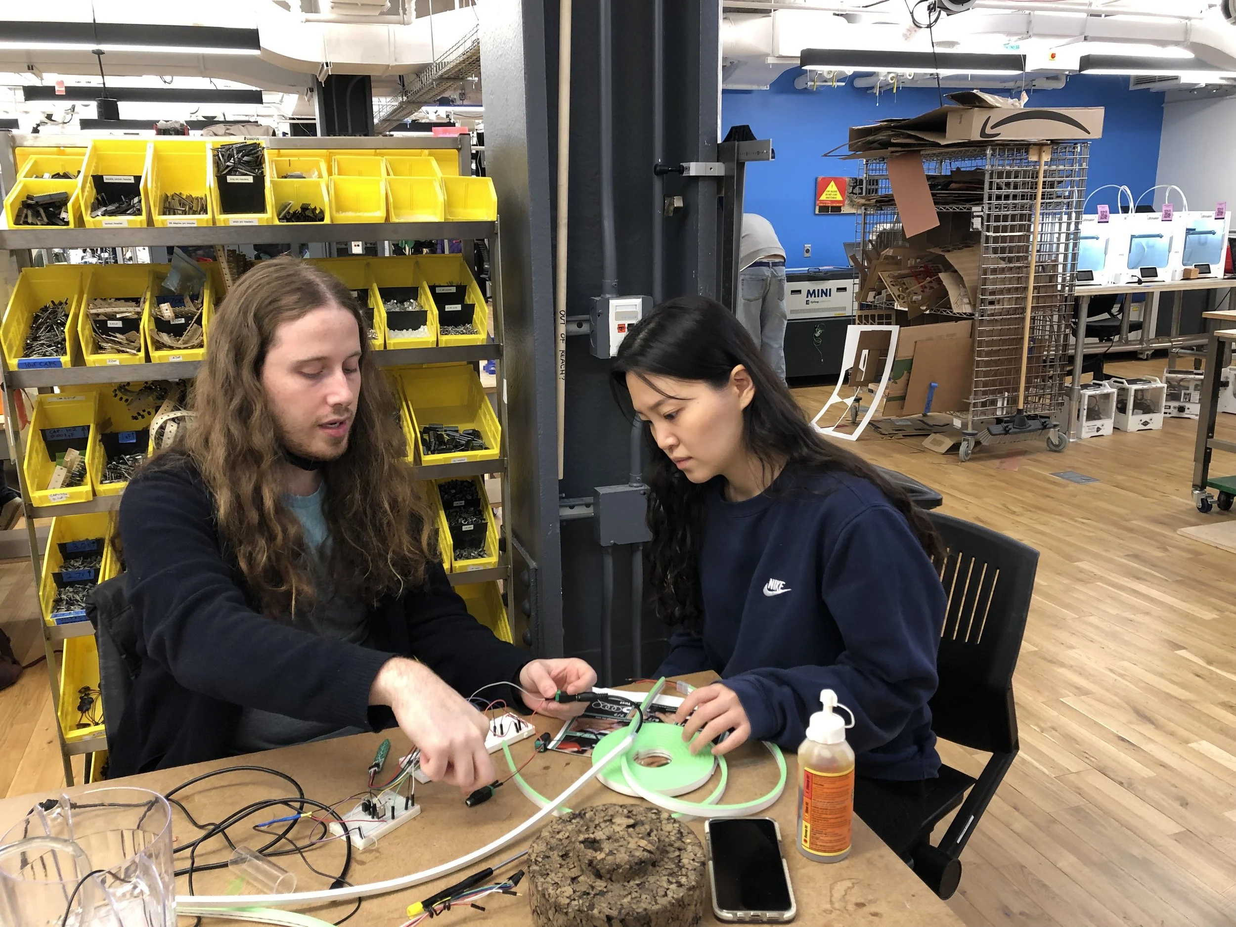
Collaboration:
Andriana Mereuta // Concept Development, Physical Computation, Code, Fabrication, Producing, Documentation
Bosung Kim // Sketching, Physical Computation, Fabrication, Producing
Instructor: David Rios
Advisors: Yonathan Rozin & Phil Caridi


The photocell, when exposed to light, activates the motor.
FINAL PROJECT WORKING!!!!
YAYYYYY!!!!
5h only today!
3 Weeks in Total!
